HOW TO MAKE [ALMOST] ANYTHING_MAS.863
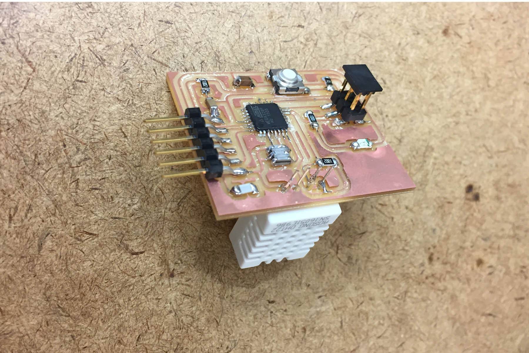
This weeks assignment was to measure something: add a sensor to a microcontroller board that you have designed and read it.
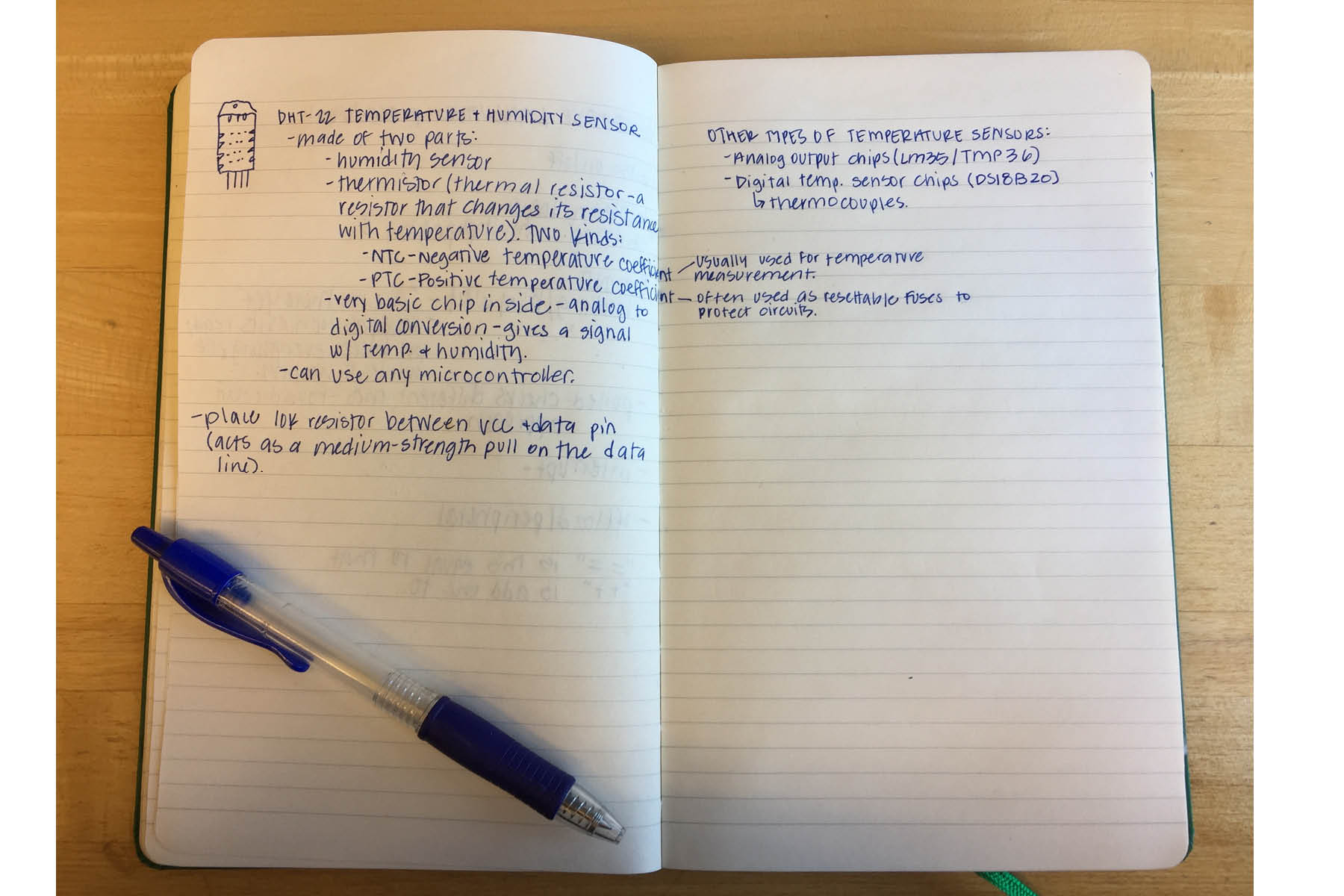
The data sheet for this sensor was much more straightforward than the ATtiny data sheet... except for all the Japanese.
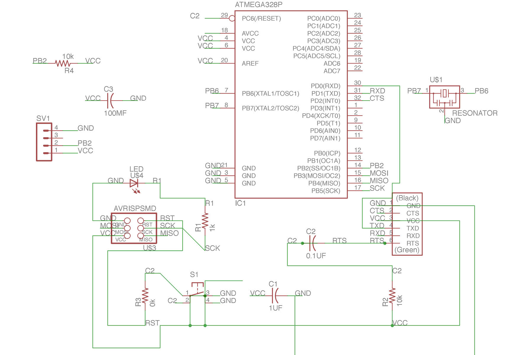
Here's the schematic from Eagle.
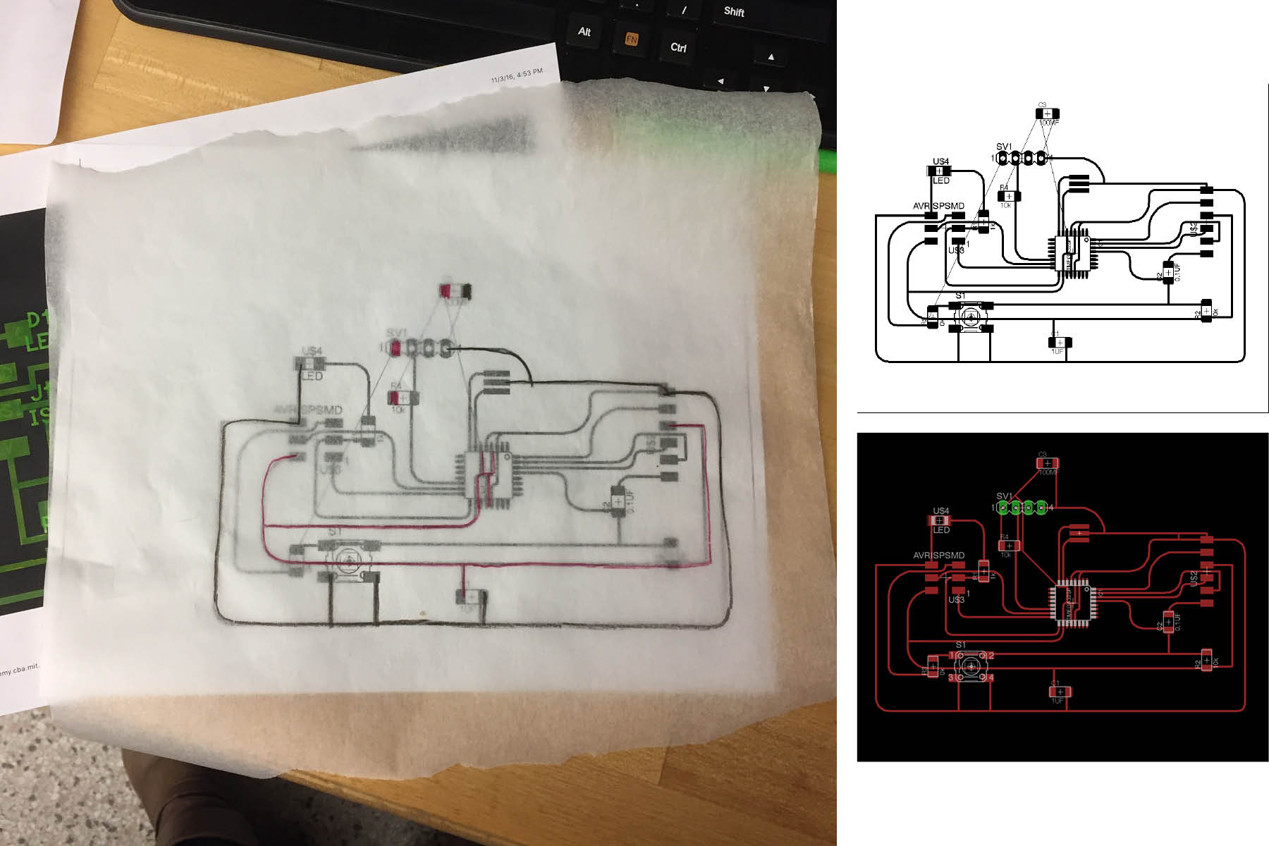
This is the most complex board I've ever designed, and I had a hard time getting all the traces in order without overlapping eachother. I did try the autorouter this time for some ideas but ended up figuring it by hand using trace paper and colored pencils (trying to keep the VCC and GND straight).
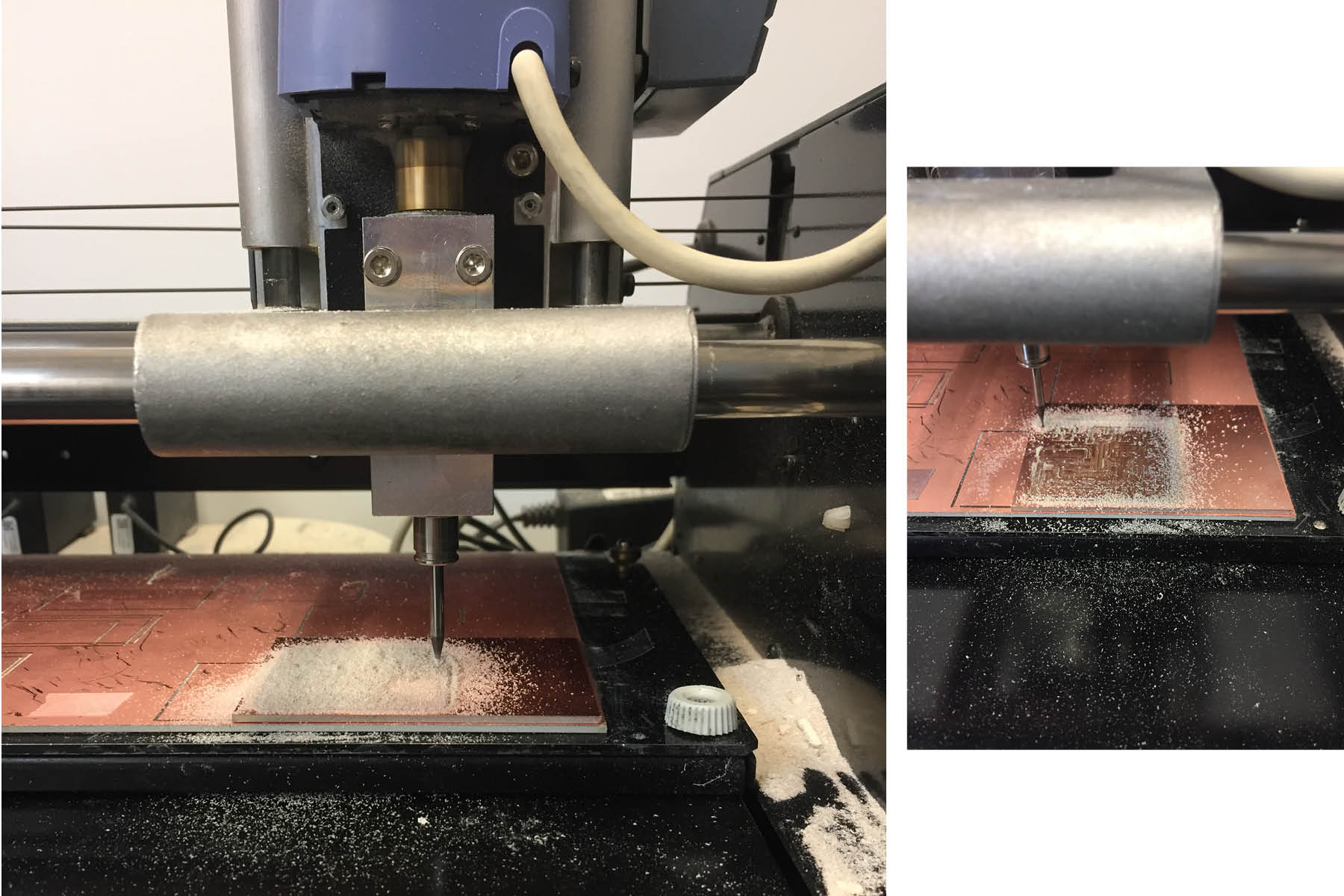
Milling feels pretty easy at this point, so I'm happy about that. If only I could stop making dumb mistakes with my files or the setup. This board took longer to cut than any of my other boards (~30 minutes for traces).
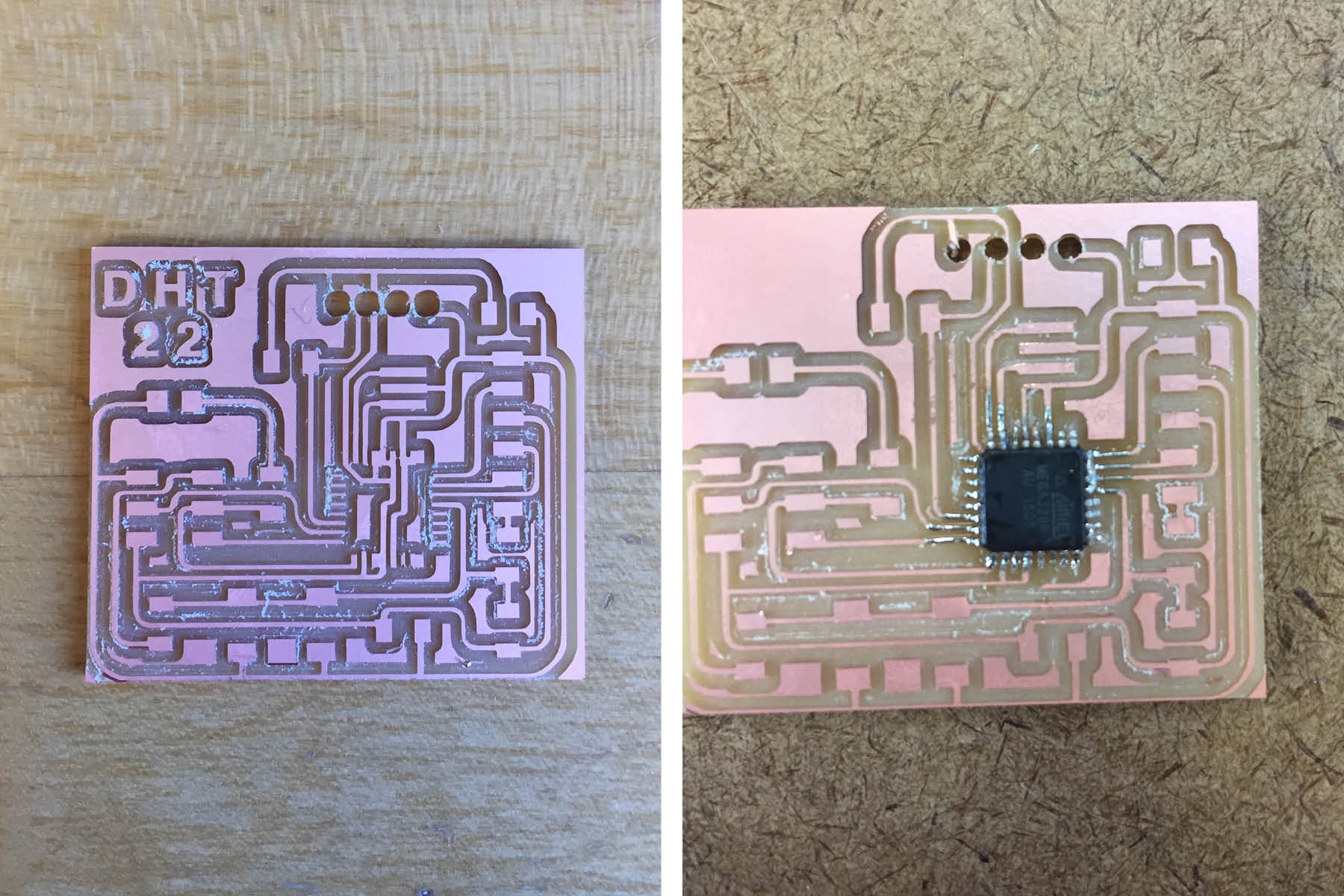
The image on the left was my first attempt. Some of the traces were too fat and there was a lot of overlap. Also, the holes that I drilled for the DHT22 were way too big.
The image on the right was my second attempt. The holes were still too big but I decided to go with it. Lesson learned here: don't solder while hungry. I had a really hard time attaching the chip - I couldn't get it lined up with the copper pads, and once I finally did, I couldn't control the solder. I tried to create a big glob and use braid to clean it up as Neil recommends, but I couldn't get the solder out from between the pins, so everything was connected. I found a bit of success in scraping the solder away with a knife and some tweezers (since the soldering iron point wasn't sharp enough) but after being a little too foreceful, I broke one of the pins and ripped the copper off the board, so it was all over after that point.
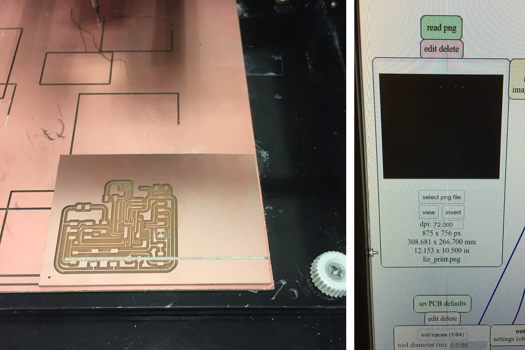
dumb dumb dumb. After making it through the traces in 30 minutes, I sent the frame .png to the mill without changing it to 500 dpi - it was on the default 72 dpi. It cut right across my traces. Bummer.


